In the figure above the gate is p region while the source and the drain are n regions. It is used to work in electronic circuits as a rectifier amplifier switch.

What Is Semantics Behind Bjt And Mosfet Transistor Symbols

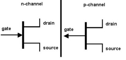
Types Of Jfet N Channel Jfet P Channel Jfet Electrical4u

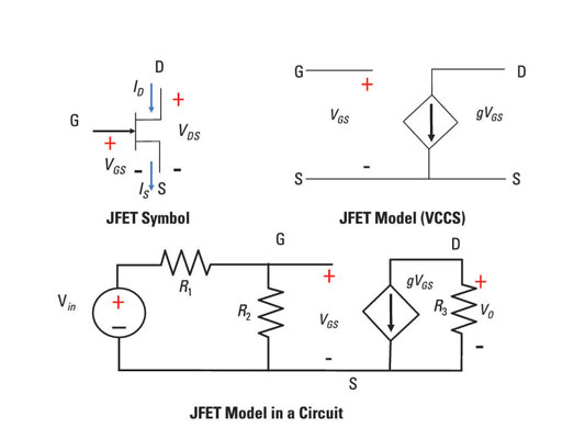
Describe A Jfet Transistor With A Dependent Source Dummies
Transistor schematic symbols of electronic circuit npn pnp darlington jfet n jfet p nmos pmos.

Transistor jfet symbol. The arrow symbol defined the emitter current. In the n p n connection we identify electrons flow into the emitter. This fundamental composition difference between npn and pnp transistors gives them different operation when controlling them.
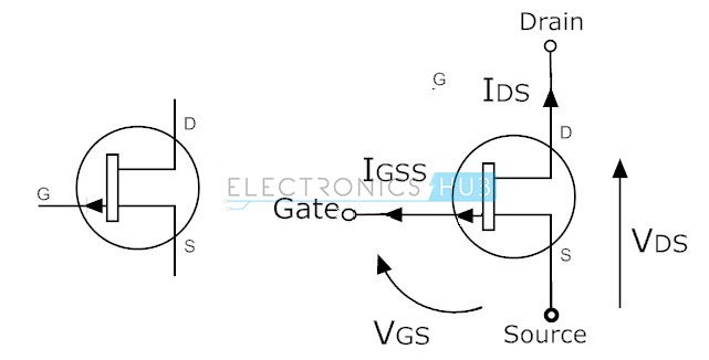
The metaloxidesemiconductor field effect transistor mosfet mos fet or mos fet also known as the metaloxidesilicon transistor mos transistor or mos is a type of insulated gate field effect transistor igfet that is fabricated by the controlled oxidation of a semiconductor typically silicon. In circuit is a connection drawn form is used. Junction fets or jfets were the first type of fet and these have a distinctive symbol showing the diode junction.
Atalla in 1959 whilst working at bell labs. The gate and the source form one of the diodes and the drain form the other diode. These two diodes are usually referred as the gate source diode and the gate drain diode.
The field effect transistor is a three terminal unipolar semiconductor device that has very similar characteristics to those of their bipolar transistor counterparts. Jfets are three terminal semiconductor devices that can be used as electronically controlled switches amplifiers or voltage controlled resistors. Obviously dual gate fets have two gates and both need to be incorporated into the circuit symbol.
Jfet transistors stand for junction field effect transistors. Table of transistor symbols. A diagrammatic form of n p n and p n p transistor is exposed.
Pnp bjts are bipolar junction transistors that are composed of 2 p material junctions and 1 n material junction. The junction gate field effect transistor jfet or jugfet is one of the simplest types of field effect transistor. Transistor symbols the transistor is a semiconductor device provided with three terminals called base emitter and collector.
A metal oxide semiconductor field effect transistor mosfet is a voltage controlled electronic component invented by a south korean engineer dawon kahng and his colleague martin m. For example high efficiency instant operation robust and cheap and can be used in most electronic circuit applications to replace their equivalent bipolar junction transistors bjt cousins. Insulated gate fets including mosfets have circuit symbols that indicate the insulation on the gate.
Because of this a jfet is similar to two diodes.

Unijunction Fet Ujt Transistor Symbol

Important Short Questions And Answers Of Fet Jfet Mosfet Bjt

What Are The Differences Between Bjt And Fet

Solved A Self Biased N Channel Jfet Has A Vd 8 V Vgs

6 Comparison Of Mosfet To Jfet Tina And Tinacloud

Field Effect Transistors Fet Homemade Circuit Projects

Figure 3 45 Jfet Structure

Jfet Electronic Symbol Field Effect Transistor Mosfet Png

Field Effect Transistors Fets

How Transistor Works And Its Types Startup Android

Fet Principles And Circuits Part 1 Nuts Volts Magazine

Transistors Junction Field Effect Jfet Circuit
Comments
Post a Comment